


Thursday 15th February 2024
Extensive
testing is conducted by optical transceiver manufacturers and qualification
engineers to ensure compliance with standards and optimal field performance.
Among the crucial tests, assessing transmitter eye-mask and receiver
sensitivity holds utmost importance in validating transceiver performance.
Receiver
sensitivity stands as a critical parameter impacting an optical transceiver's
functionality. It denotes a module's capability to function in challenging
environments and aids network operators in determining the system's maximum
reach or link margin.
Measurement
of Receiver Sensitivity
Receiver
sensitivity is defined by how weak an input signal can be to prevent
the Bit Error Rate (BER) from exceeding
a specific value which is
set by the
MSA standards. Exceeding the BER value indicates signal degradation, rendering it
unsuitable for data communication. In other words the
receiver sensitivity is the minimum average optical power in dBm needed to
obtain a minimum BER value. The BER values are usually :
- < 2.4 x 10⁻⁴ (PAM4)
- < 5 x 10⁻⁵ (NRZ)
- < 2.4 x 10⁻¹² (after FEC)
Unstressed
vs Stressed Receiver Sensitivity
For the stressed
receiver sensitivity testing, a degraded signal is transmitted over the fiber
by introducing factors such as poor extinction ratios, various jitter types,
and inter-symbol interference (ISI). The module succeeds if the minimum receive
power at a specific BER remains within acceptable levels. Stressed
receiver sensitivity (SRS), expressed as :
- OMA (dBm).
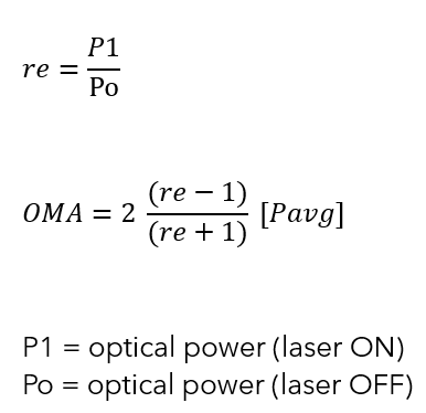
Calculating Sensitivity
Optical Modulation Amplitude (OMA) can be calculated using Average Power (Pavg) and Extinction Ratio (re). Average power measurement is facilitated by an Optical Power Meter, while the extinction ratio is determined using an oscilloscope, enabling accurate OMA calculation.
Stressed Receiver sensitivity Test Configuration
A common test setup to evaluate Stressed Receiver Sensitivity involves measuring the Optical Modulation Amplitude (OMA) using a square wave, per the standard guidelines. This precedes the introduction of Inter-Symbol Interference (ISI), Sinusoidal Amplitude Interference (SI), and Sinusoidal Jitter (SJ). In cases where a square wave isn't available, approximating the OMA of a Pseudo Random Binary Sequence (PRBS) signal becomes necessary, as depicted in the accompanying eye diagram.
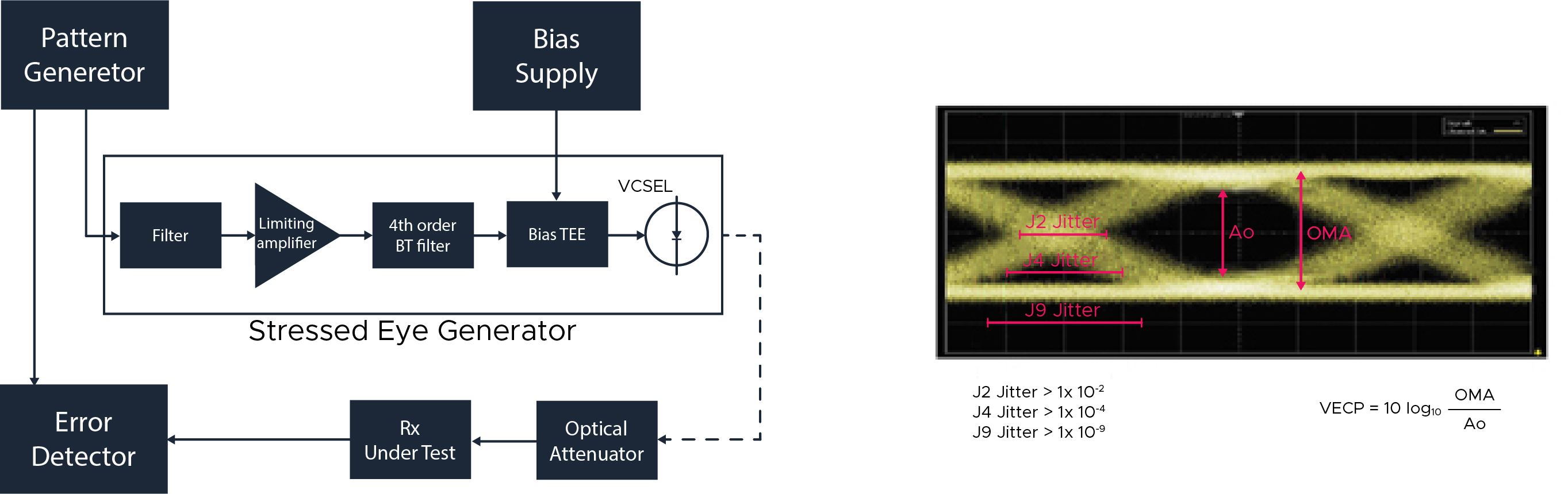
To produce an SRS signal using the transceiver
- Run the sinusoidal jitter (both horizontally and vertically) exceeding
40 MHz while
using a poor extinction ratio and adding inter-symbol interference (ISI).
- Utilize a low-pass filter,
specifically a 4th-order Bessel-Thomson roll-off filter, to lower
the high-frequency components (VECP).
- Measure the OMA as a
function of the receiver at BER 1x10-12 or 1x10⁻⁵, following
the MSA specifications.
Conclusion
and Recommendations
Comprehensive
testing, as per standards, aids in selecting transceiver vendors and validating
equipment performance in adverse conditions. Such meticulous assessment ensures
optimal transceiver functionality and reliability in real-world deployment
scenarios.